The Coastal Rescue Society is working to improve its performance in the delivery of rescue equipment to vessels in distress. The most common configuration for delivery includes a rescue/salvage pump along with a rescue kit containing plugging/patching supplies, life preservers, food, water and flares. The society has recently acquired a system for delivery of this equipment that is designed to be dropped from a small airplane.

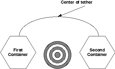
The new system consists of two soft-sided containers with attached drogue parachutes connected by a variable length tether. The first soft-sided container is designed to house the rescue/salvage pump; the rescue kit is placed in the second. The tether is a floatable line that can be adjusted in length from 100 to 400 feet with a targeting mark attached to its center. When dropping the system to a vessel in distress, the intention is to drop the containers on a course into the wind so that the first one drops on one side of the vessel and the other drops on the opposite side, with the center of the tether on the vessel. The figure to the right roughly depicts the system (without the parachutes) when properly deployed.
The trick to properly deploying the system is to accurately estimate when to drop the initial container so that the entire system can be deployed to straddle the vessel in distress without hitting it and causing further damage. Once the tether is across the vessel, the people on board can haul in the containers to retrieve the rescue equipment.
Factors associated with estimating the drop parameters are:
Your task is to develop a tool that can be used to estimate, based on the given drop parameters, the time and distance from a distressed vessel that the system must be dropped to ensure that the tether properly straddles the vessel. In addition to its use as an estimating tool, the solution will be designed to be used in training pilots to learn about drop operations. This will be supported by an interactive graphical display that provides a time stepped plot of the system throughout its deployment.
The end of input is denoted by a data set identification of "Done" not followed by any data.


"Case 1"
0.5 150 500 045 10 32.1 0.1 100 300
"Done"
Line 1 of the sample input contains the data set identification for the data set to be analyzed. Line 2 provides the data for the drop parameters. They specify that the graphical plot will include displays at half-second intervals, the aircraft has a velocity of 150 knots and an altitude of 500 feet during the drop, and the wind is from 45 degrees at 10 knots. The containers will accelerate at 32.1 feet/second2 vertically and the horizontal drag factor is 0.1. The maximum vertical velocity is 100 feet per second and the tether has been adjusted to 300 feet in length. Line 3 of the sample input contains the end of input sentinel "Done". Output The output for your solution consists of lines in an output file and an interactive graphical display of the simulated results for each data set. File output will be placed in a file named pumpdrop.out in the current directory. Desired output for the sample input is shown below: The case identification information precedes the header which includes the wind direction (no fractional digits), aircraft speed (in feet per second; two fractional digits), the distance from the distressed vessel at which the first container is dropped (one fractional digit), and the time required for the first container to reach the surface (two fractional digits). Each of the lines after the header includes the time (in seconds) after the drop and pairs giving the horizontal and vertical distance from the distressed vessel of the first container, middle of the tether, and the second container. These values are to be displayed with one fractional digit.
==================================================
Case 1
==================================================
Drop Run 45 Degrees @ 236.29 fps
Estimated Drop Advance 1396.0 at time T - 7.87 secs
Time   (Start X,Y)     (Mid X,Y)     (End X,Y)
==================================================
0.0   (-1396.0,500.0)    (-1396.0,500.0)    (-1396.0,500.0)
0.5   (-1280.9,496.2)    (-1279.4,498.1)    (-1277.8,500.0)
1.0   (-1171.9,485.5)    (-1165.8,492.8)    (-1159.7,500.0)
1.5   (-1068.6,469.0)    (-1055.1,484.5)    (-1041.5,500.0)
2.0   (-970.8,447.6)    (-947.1,473.8)    (-923.4,500.0)
2.5   (-878.1,421.9)    (-841.7,460.9)    (-805.2,500.0)
3.0   (-790.4,392.6)    (-738.7,446.3)    (-687.1,500.0)
3.5   (-707.4,360.2)    (-638.2,430.1)    (-568.9,500.0)
4.0   (-628.8,325.3)    (-539.8,412.6)    (-450.8,500.0)
4.5   (-554.5,288.0)    (-446.0,391.6)    (-337.5,495.2)
5.0   (-484.2,248.9)    (-374.2,350.9)    (-264.1,452.8)
5.5   (-417.7,208.2)    (-306.0,308.3)    (-194.3,408.4)
6.0   (-354.9,166.1)    (-241.5,264.3)    (-128.0,362.4)
6.5   (-295.6,122.9)    (-180.5,219.0)    (-65.4,315.2)
7.0   (-239.6,78.6)    (-122.9,172.8)    (-6.1,266.9)
7.5   (-186.7,33.5)    (-68.4,125.7)    (49.8,218.0)
8.0   (-150.0,0.0)    (-25.0,83.0)    (99.9,165.9)
8.5   (-150.0,0.0)    (-9.8,53.3)    (130.4,106.6)
9.0   (-150.0,0.0)    (-2.3,26.1)    (145.4,52.2)
9.5   (-150.0,0.0)    (0.0,3.2)    (149.9,6.3)
10.0   (-150.0,0.0)    (0.0,0.0)    (150.0,0.0)
Drop Complete

==================================================
All Data Sets Complete
==================================================

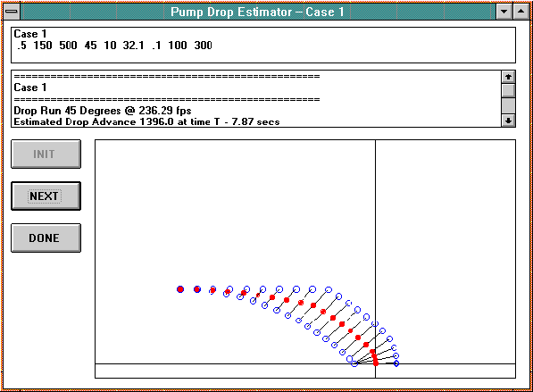
The interactive graphical display as shown to the right consists of a form with three frames or designated areas on the screen. The Echo Input area will include a scrollable list box which echoes the information from the input file. The Echo Output area will include a scrollable list box which echoes the information included in the output file. The Plot Area contains a graphical depiction of the drop scenario scaled to (2000 feet to +500 feet horizontally by +1500feet to (100 feet vertically with horizontal and vertical axes plotted as shown.
The plot for the deployed system shall clearly display the two containers, the tether line, and its midpoint.
You must include an INIT button to activate program setup and initialization functions, a NEXT button to activate processing and display of the next (or first) data set, and a DONE button to clean up program functions and exit. The plot for each data set must remain visible until the NEXT or DONE button is clicked.